Matty
Aldridge
I design aerospace and motorsport hardware: parametric CAD in SolidWorks, Fusion and Python, backed by stress, flow and thermal studies that I always check against a hand calculation.
These sheets cover six projects, including work for my university Formula Student team and rocketry society.
Formula Student drivetrain
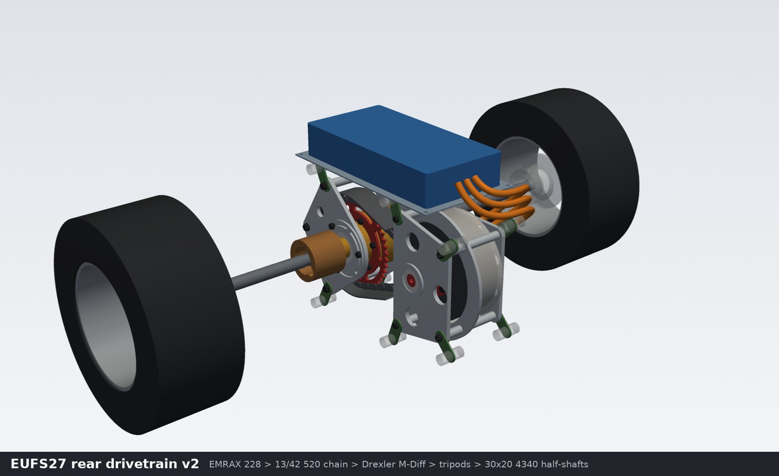
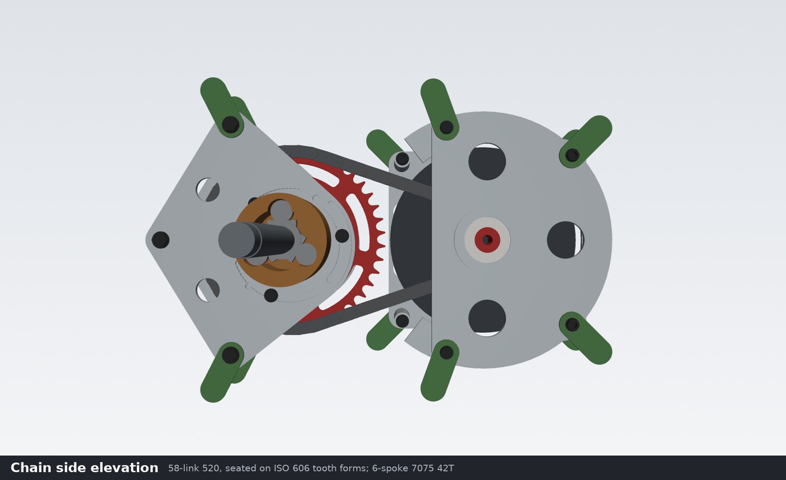
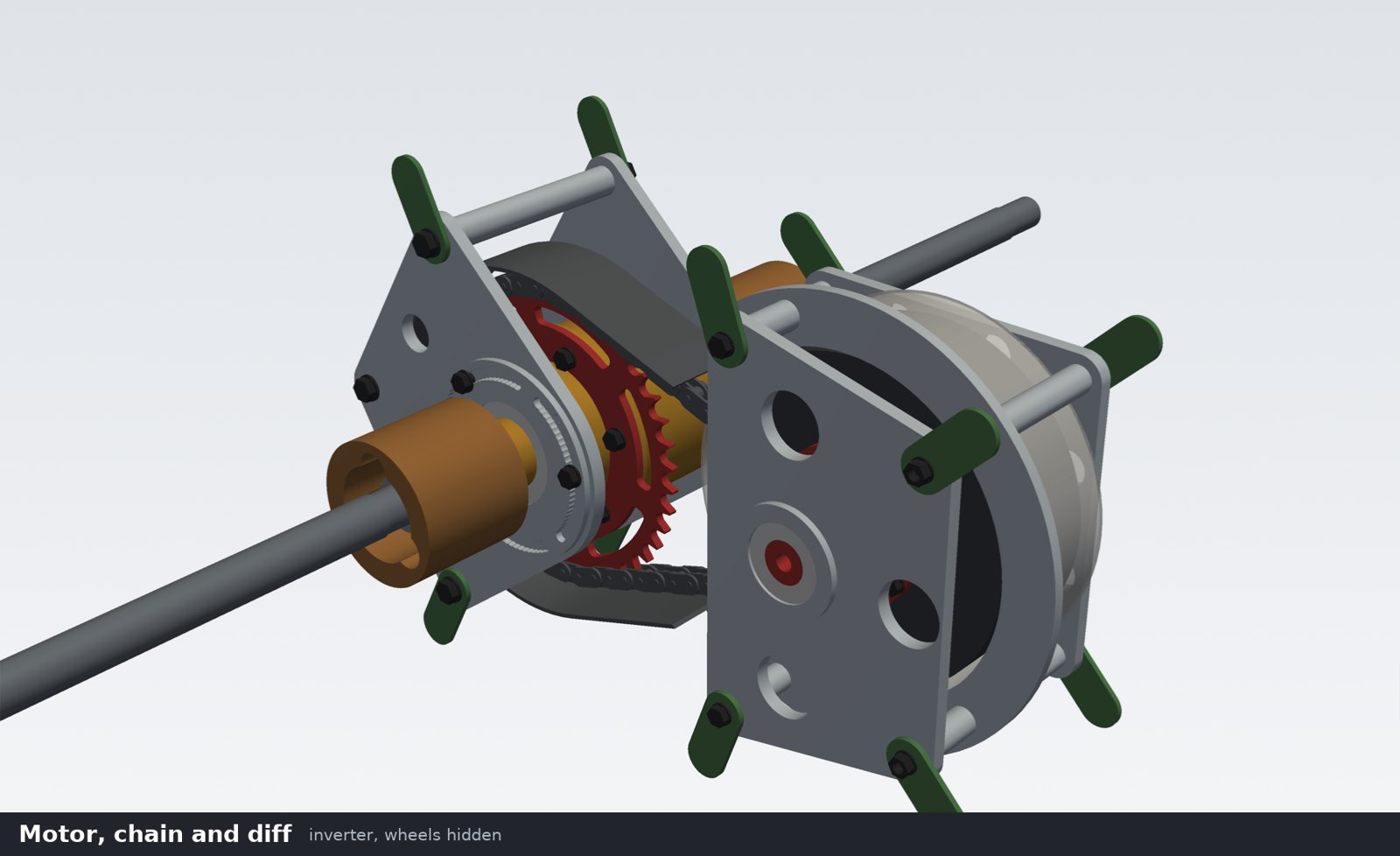
EUFS 2027 car · conceptA chain-drive rear powertrain package for the university team's 2027 electric car: motor cradle, outrigger bearing, eccentric diff carriers, sprocket and half-shafts, built as a full SolidWorks assembly.
| Reduction | 13:42 (3.23) |
| Diff torque, design | 1,066 N·m (×1.5 shock) |
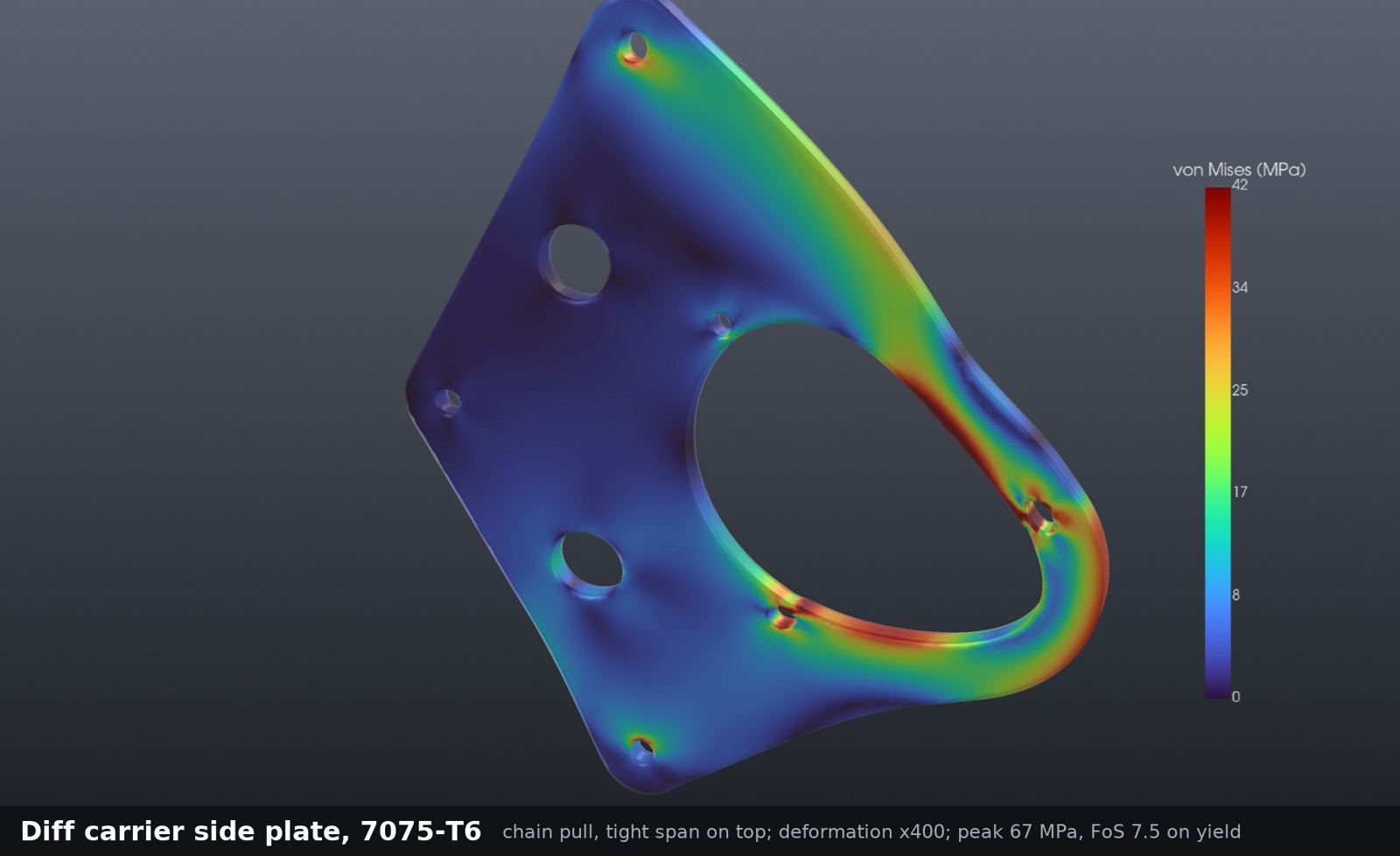
| Chain pull, design | 9.95 kN |
| Half-shaft | 30 × 20 mm 4340 tube |
| Half-shaft FoS | 1.98 static · 1.71 fatigue |
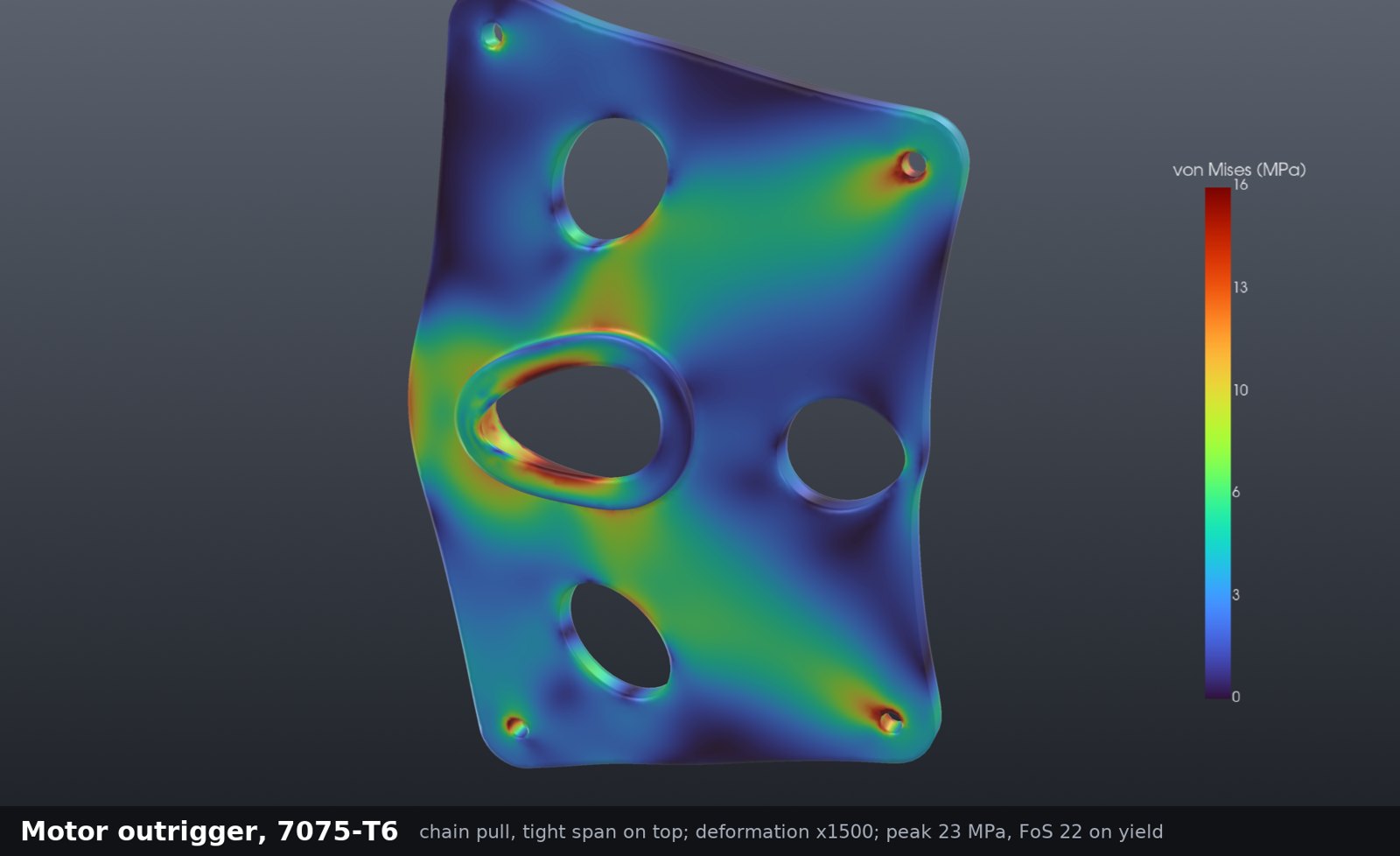
| Diff plate FoS on yield | 7.5 |
Every mount passes. The 42-tooth sprocket's window corners set the limit, at a yield FoS of 1.32 after rev B, so the next step is a thicker or solid web. This is a concept for my subteam, not the final car.
- Mechanical powertrain engineer on Edinburgh University Formula Student (EUFS).
- Packaged the motor cradle, outrigger, eccentric diff carriers, sprocket and half-shafts as a native SolidWorks 2026 assembly around the team's chosen motor, diff and inverter.
- Hand calcs for shafts, splines, bolts and bearings; CalculiX FEA of the plates and sprocket.
Hall-effect thruster
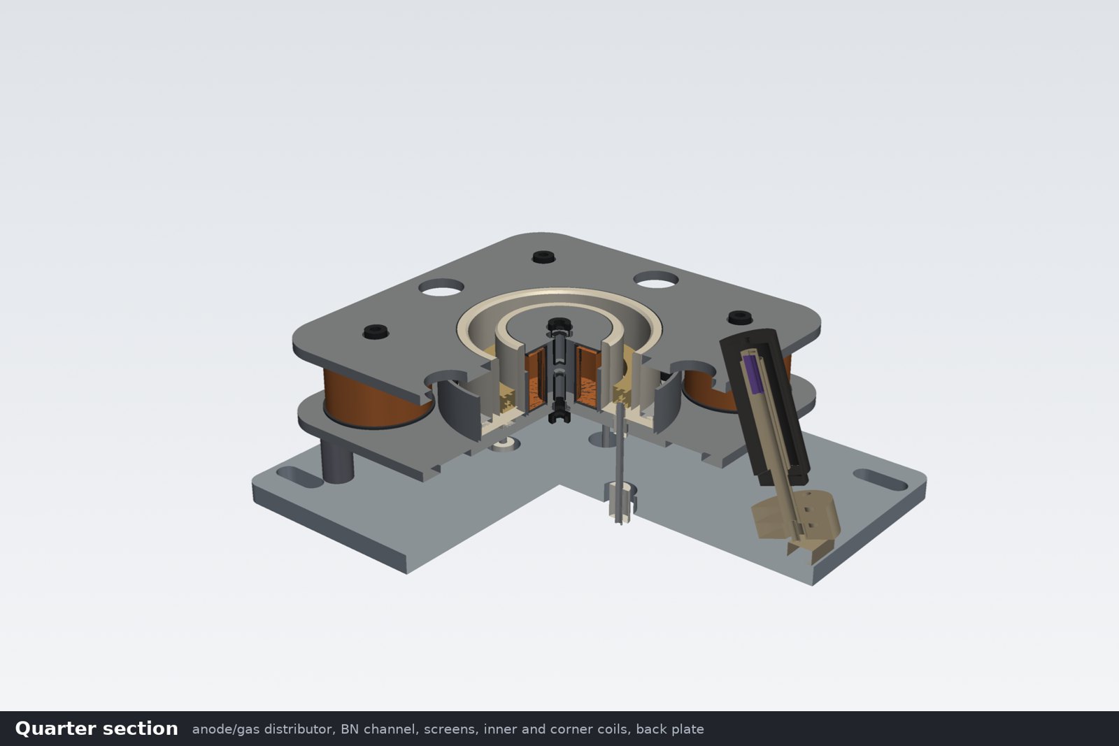
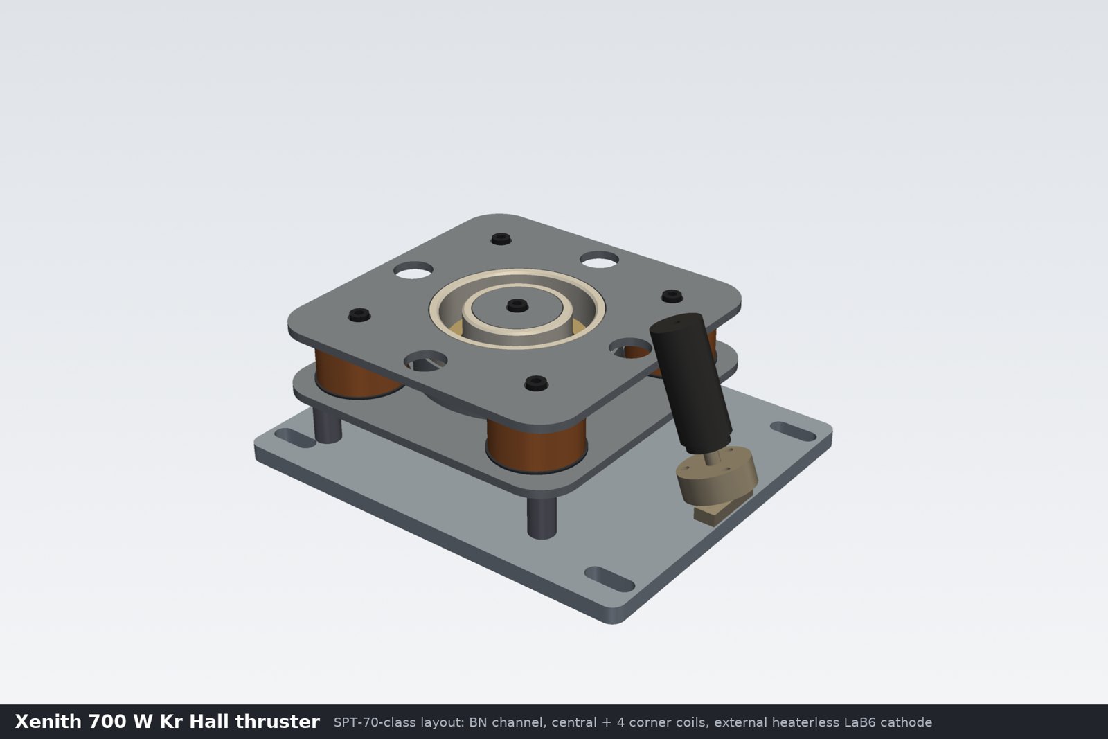
700 W, krypton · EndeavourA Hall thruster for Project Xenith, the Edinburgh University rocketry society's plan to fire a student-built thruster at Race 2 Space. Boron nitride channel, iron magnetic circuit with five coils, heaterless hollow cathode.
| Power | 700 W |
| Propellant | Krypton |
| Channel | OD 68 / ID 48 mm |
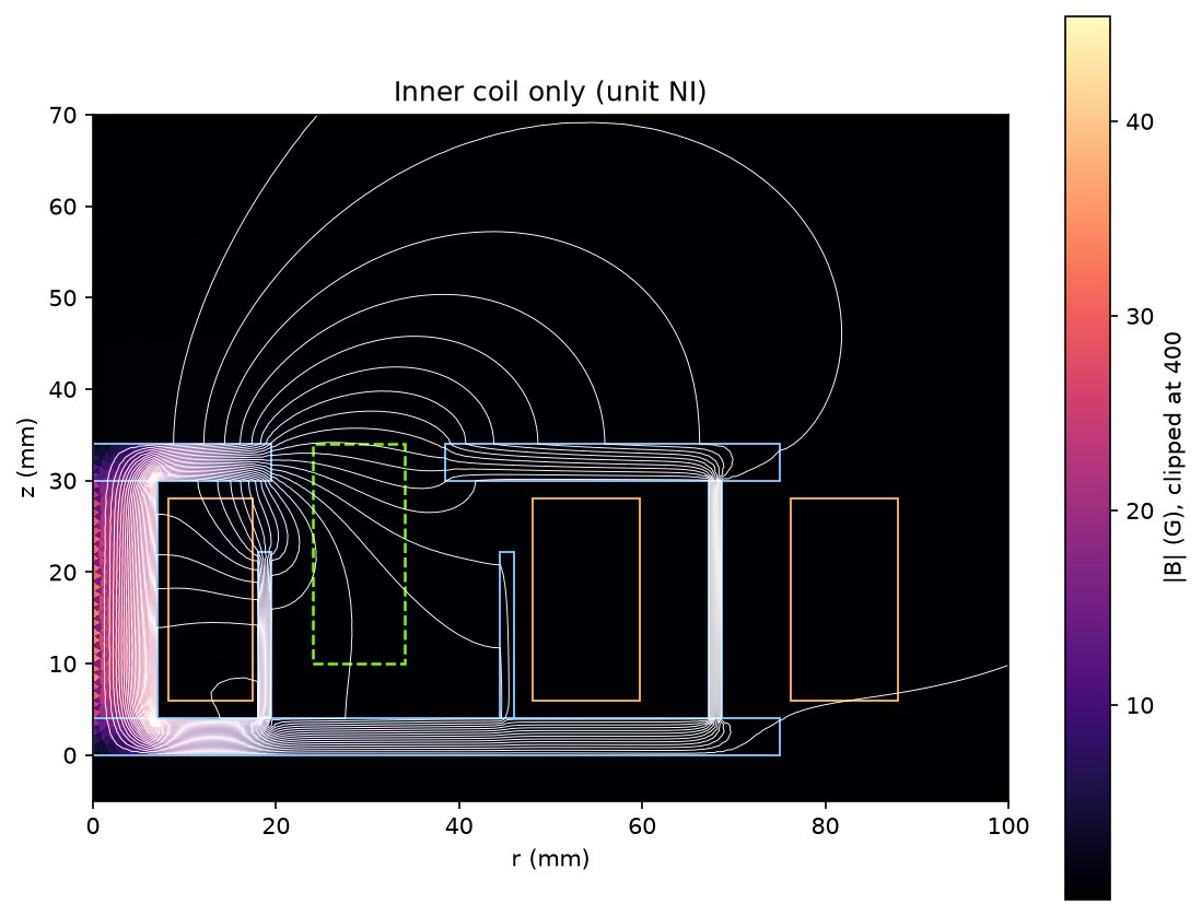
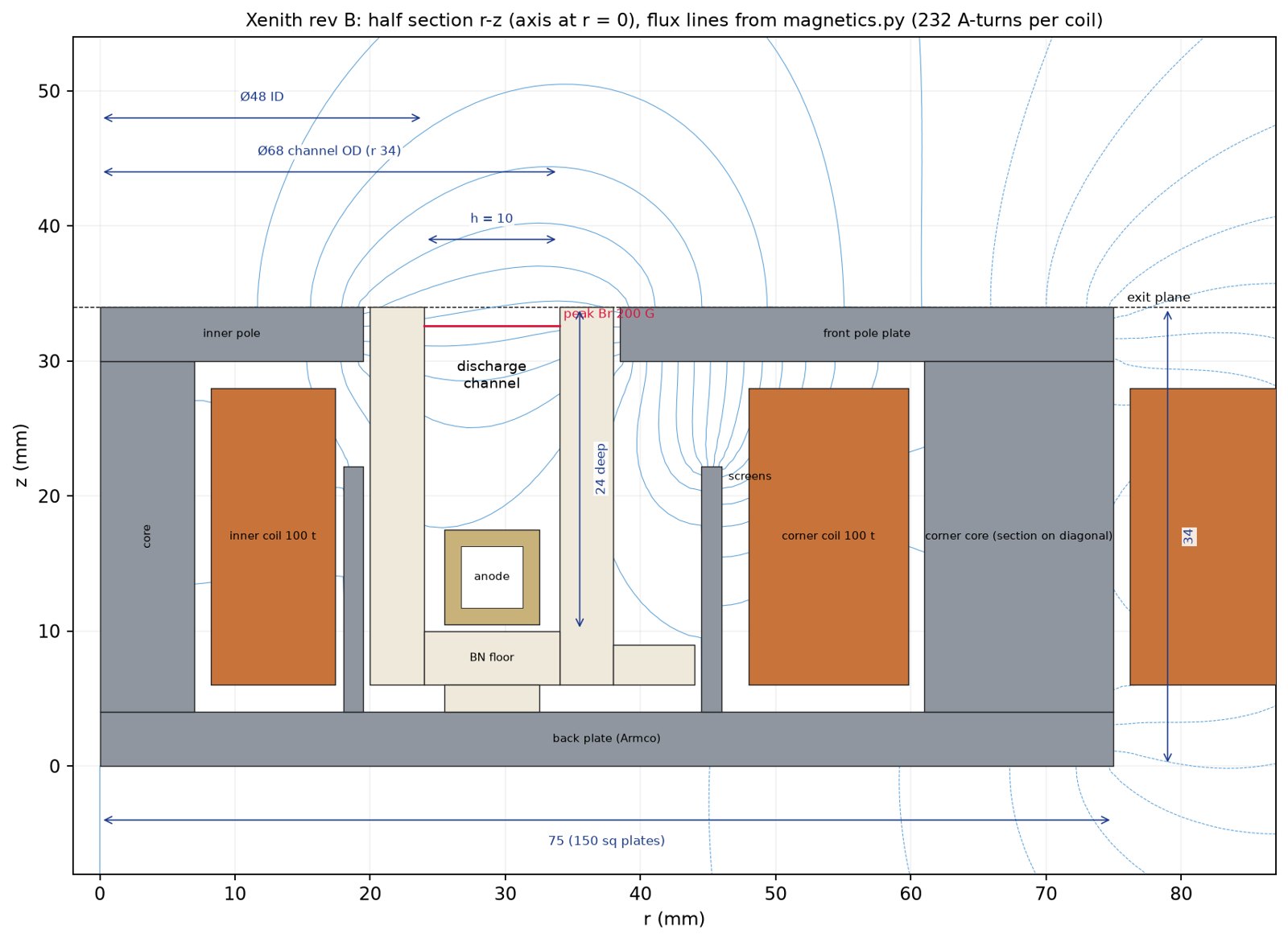
| Peak radial field | 200 G |
| Field model vs analytic | −0.13 % |
| Anode temperature, est. | ~665 °C |
The thermal network puts the inner coil at about 400 °C, well past polyimide-insulated wire, so it needs ceramic-insulated wire. Hardware tests come next: cold flow, field mapping and the cathode.
- Thermal-mechanical engineer on Project Xenith, a 13-student team in Endeavour.
- Sized the thruster from SPT scaling laws and modelled it in SolidWorks with a full bill of materials.
- Wrote an axisymmetric magnetics FEM, checked against an analytic solenoid, and a radiation and conduction thermal network.
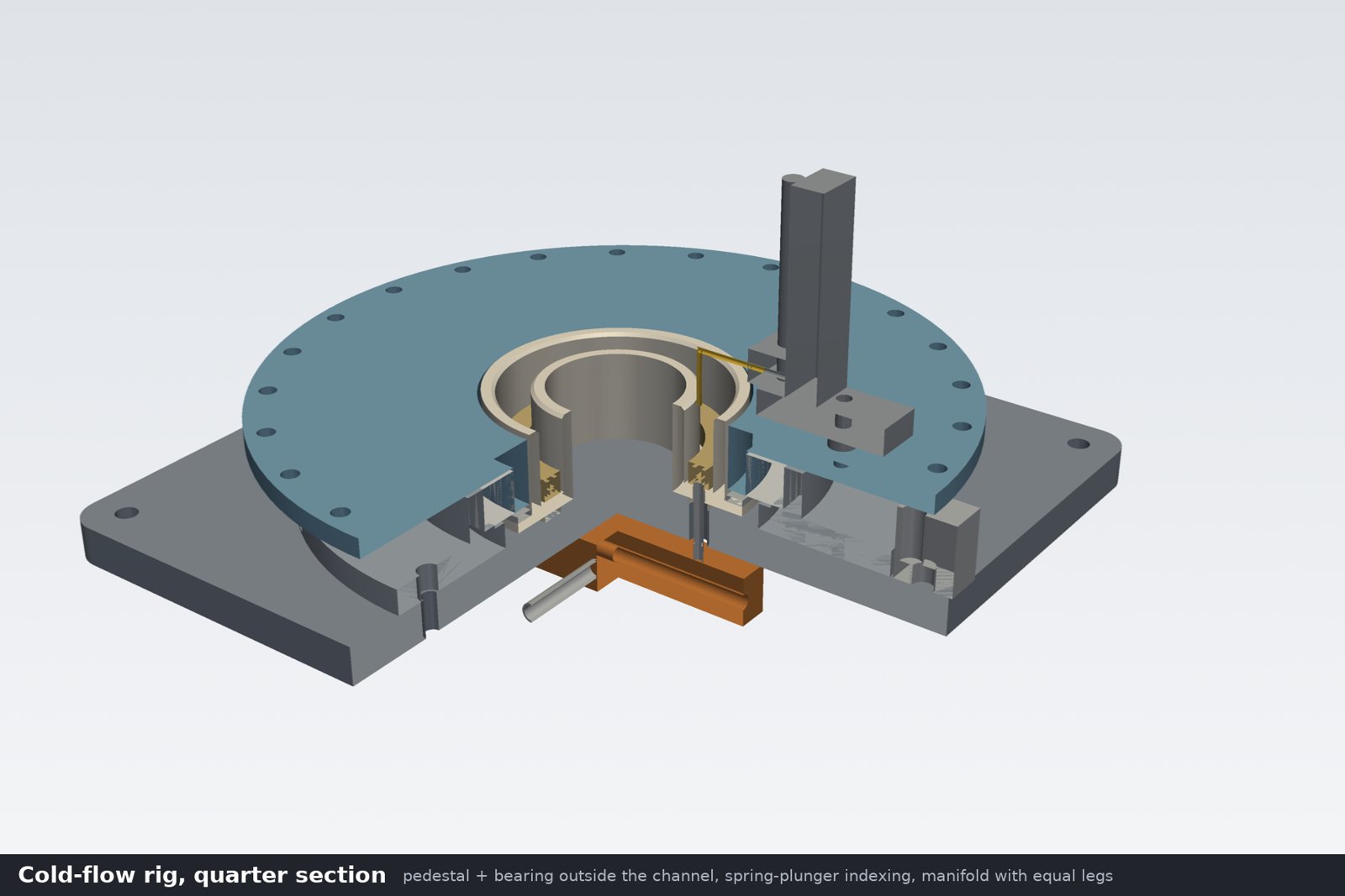
- Designed the cold-flow test rig.
Supersonic intake
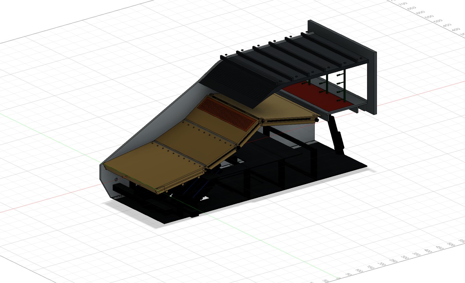
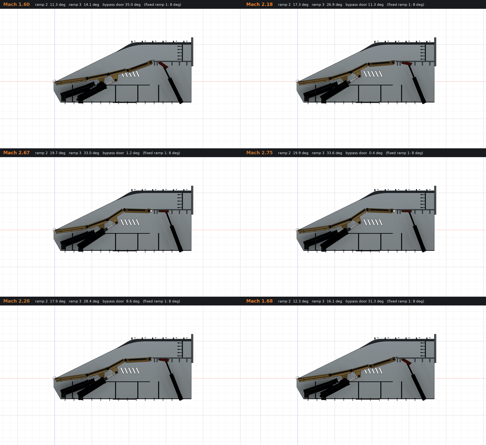
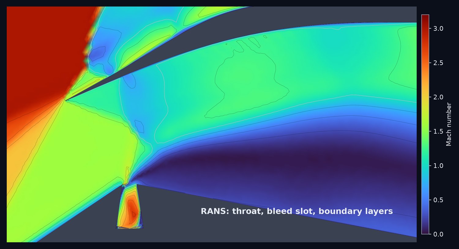
Mach 1.6 to 3.0An air intake that changes shape across its speed range so the engine always gets slowed, high-pressure air.
| Capture area | 200 × 300 mm |
| Ramps | 3 (2 variable) |
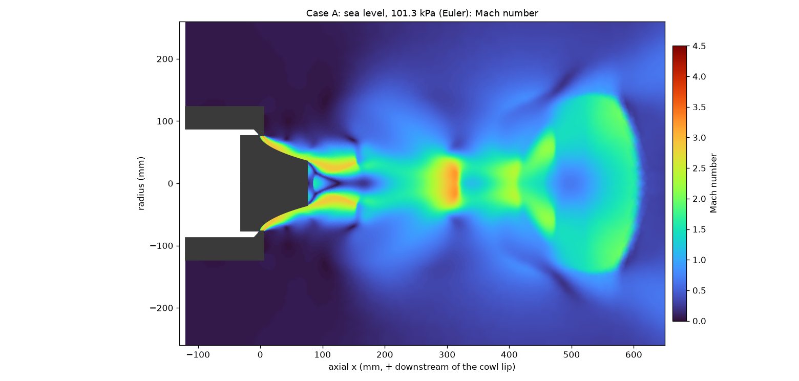
| Pressure recovery, Mach 3 | 0.833 (MIL spec 0.809) |
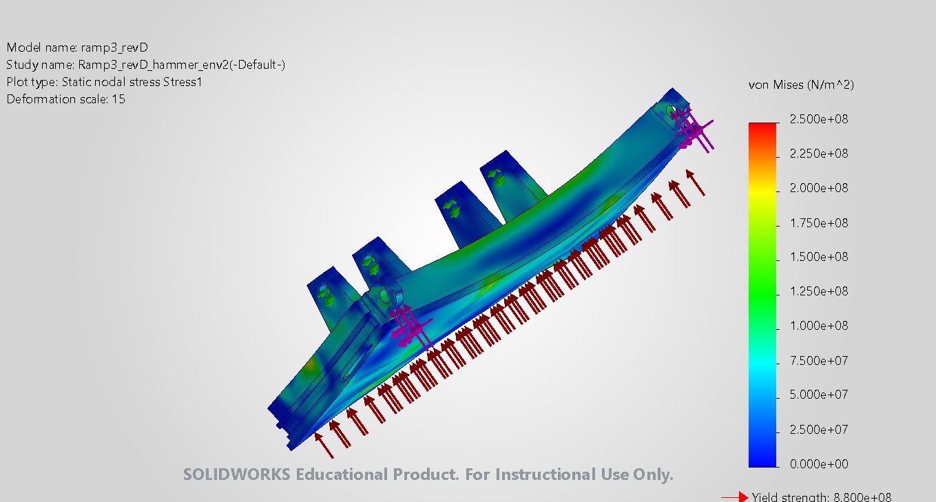
| Actuator surge load | 12.9 kN |
| Ramp 3 stress, p99 | 136 MPa |
Meets the spec at Mach 3. At Mach 2.0 and 2.4 it falls short because the cowl lip is fixed; a moving lip is the next step.
- Set the requirements: Mach 1.6–3.0, moving ramps on ballscrews, seals, bleed plate and bypass door.
- Worked out the shock schedule, which pushed the design from two ramps to three.
- Built the CAD and Fusion assembly, clash-checked at every ramp position.
- Ran SU2 CFD across the range after validating it on the Sajben case; ramp FEA and actuator hand calcs.
Rocket hop vehicle
VTVL, electric pump-fed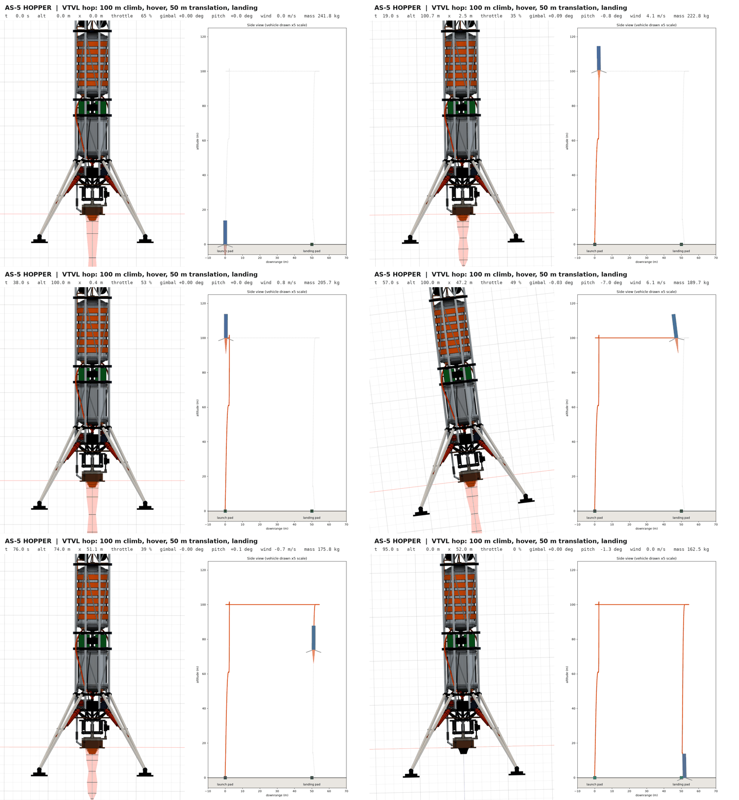
A vertical take-off and landing test vehicle built around the aerospike in Sheet 5.
| Take-off mass | 242 kg |
| Thrust to weight | 1.62 |
| Hop apogee | 101.6 m |
| Landing error | 2.0 m |
| Parts in Fusion | 45 |
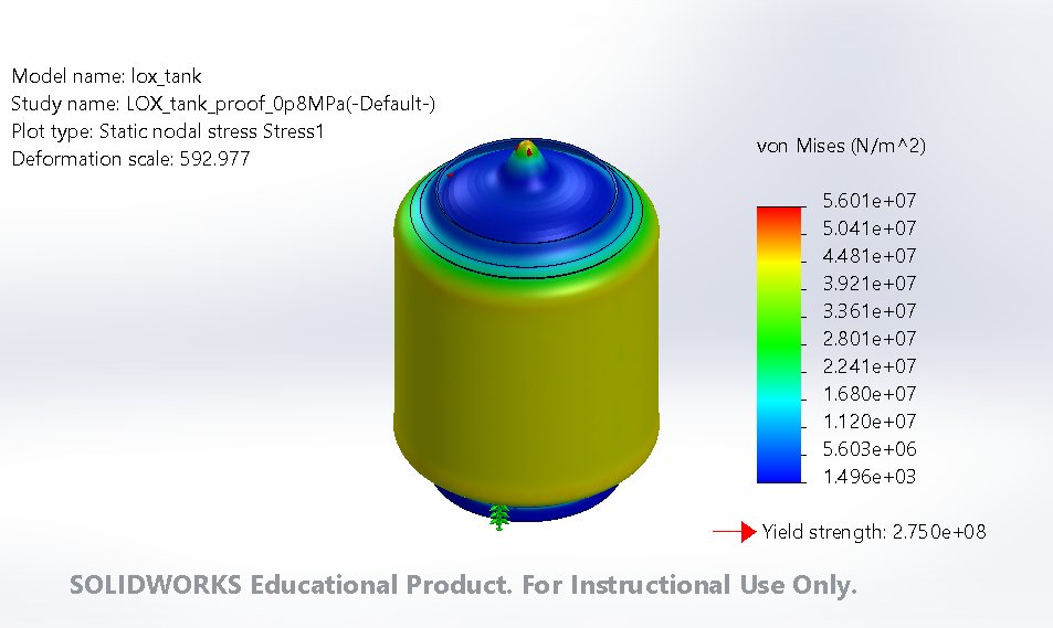
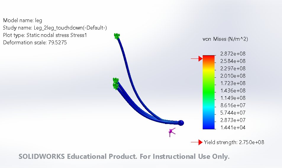
Every structure passes with margin. The oxygen pump gets only 1.34× the suction head it needs, so it needs an inducer.
- Chose the concept: a hop vehicle with electric pumps, built around the Sheet 5 aerospike.
- Sized it and built a 45-part Fusion assembly, checked in SolidWorks.
- Wrote a 3-DOF flight sim with attitude control.
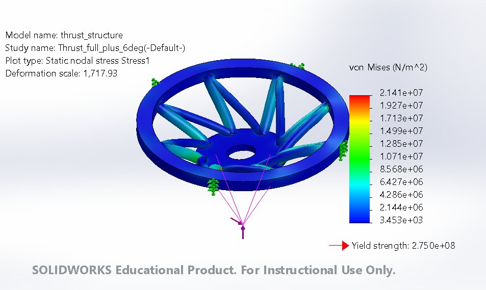
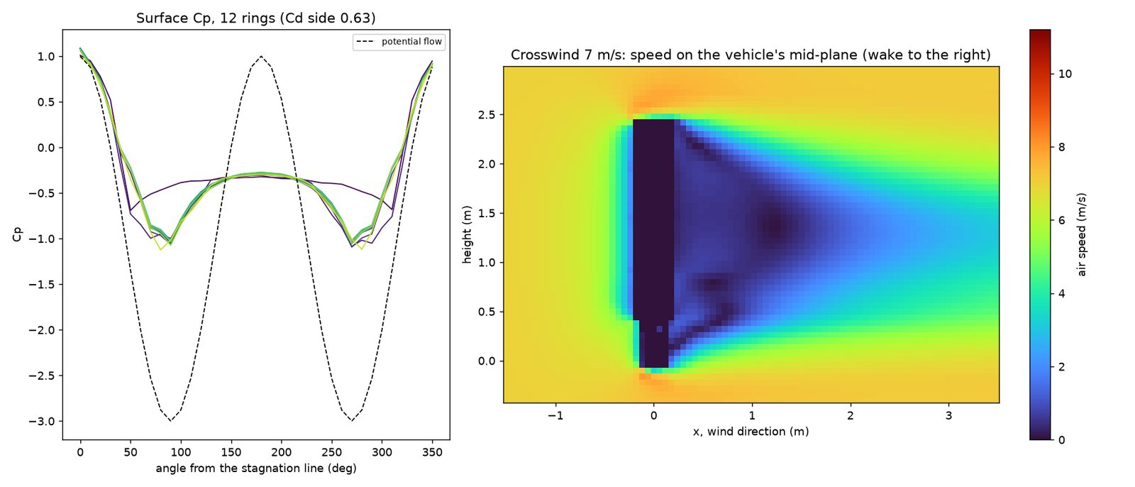
- FEA of the thrust structure, tank and legs; crosswind and feed-line CFD.
Aerospike engine
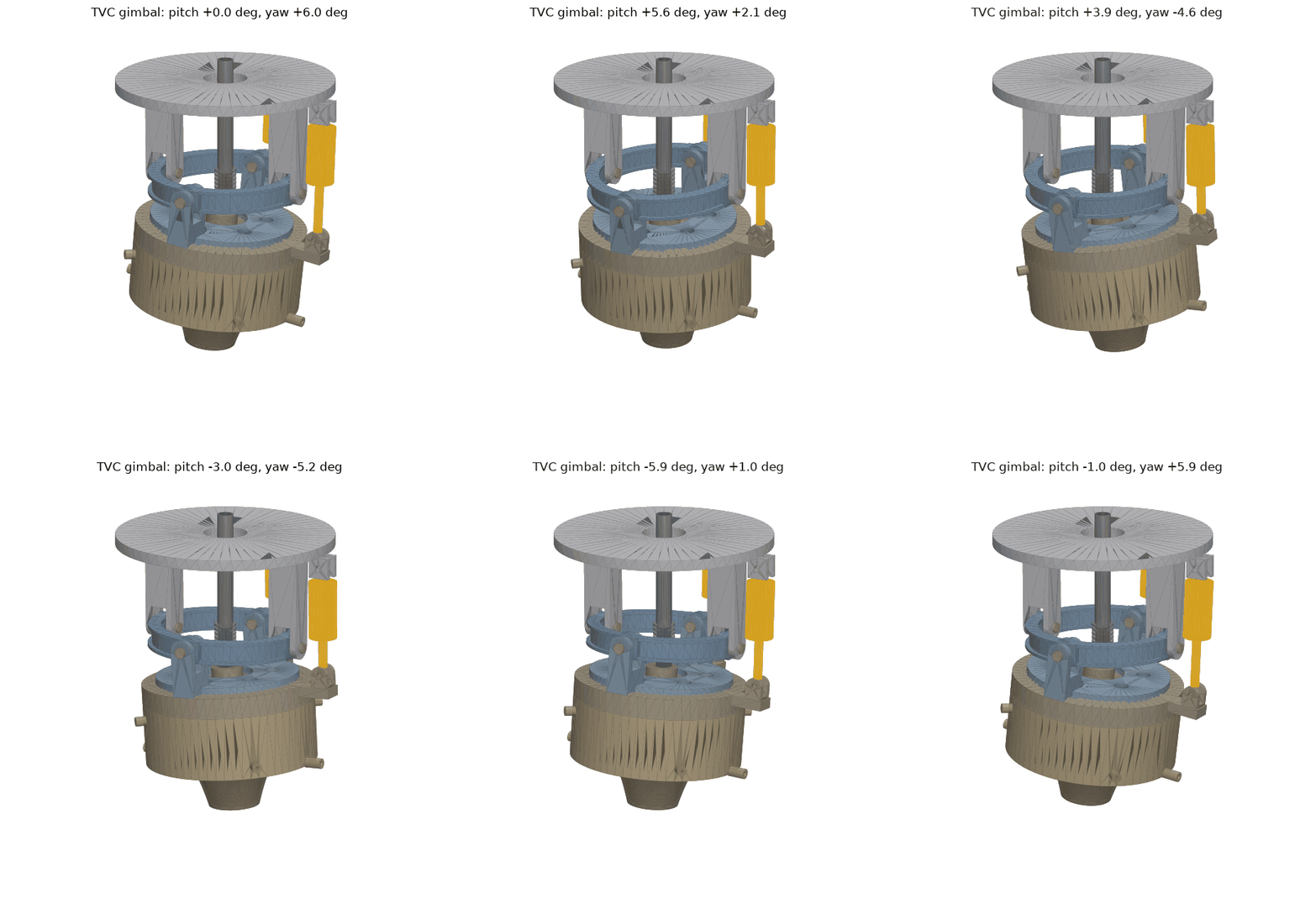
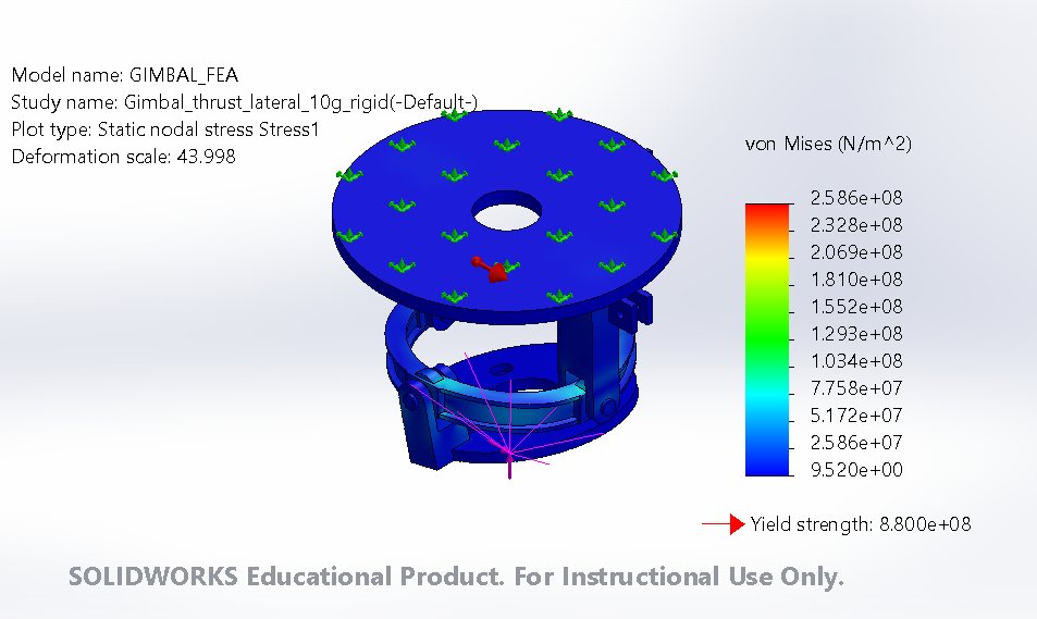
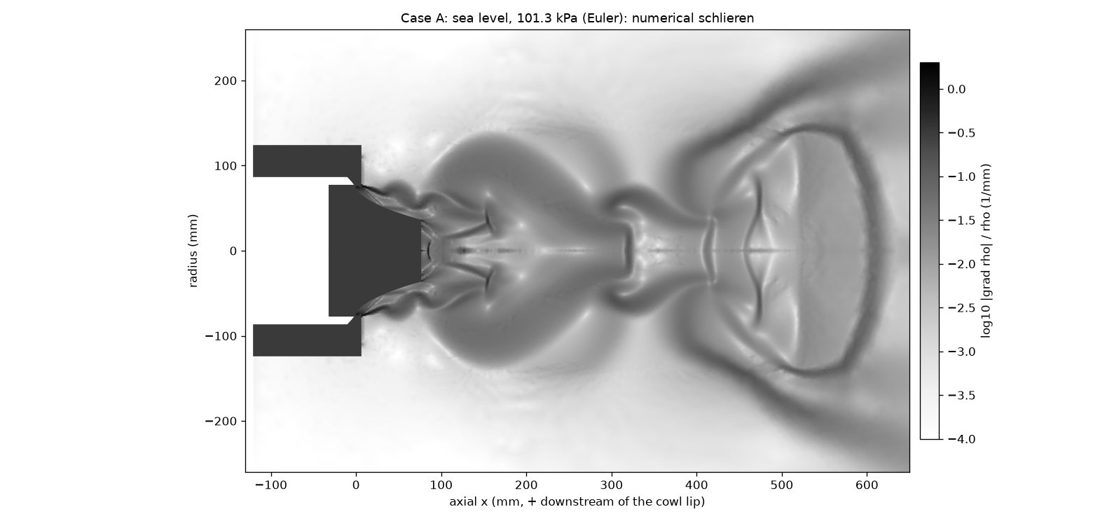
5 kN, LOX / RP-1An annular aerospike on a gimbal that steers it 6° in any direction.
| Thrust, sea level | 3.83 kN |
| Thrust, altitude | 5.0 kN |
| Gimbal FoS | 3.4 |
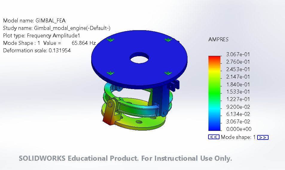
| First mode | 66 Hz |
Structurally sound, thermally not. Regen cooling can carry 0.46 MW against 0.9 MW in, so the cooling concept has to change.
- Designed a 5 kN annular aerospike with regenerative cooling on a two-ring gimbal.
- Gimbal kinematics and actuator sizing.
- Plume CFD checked against Angelino's method; gimbal FEA and modal analysis; a cooling-channel optimiser.
EV corner module
7075-T6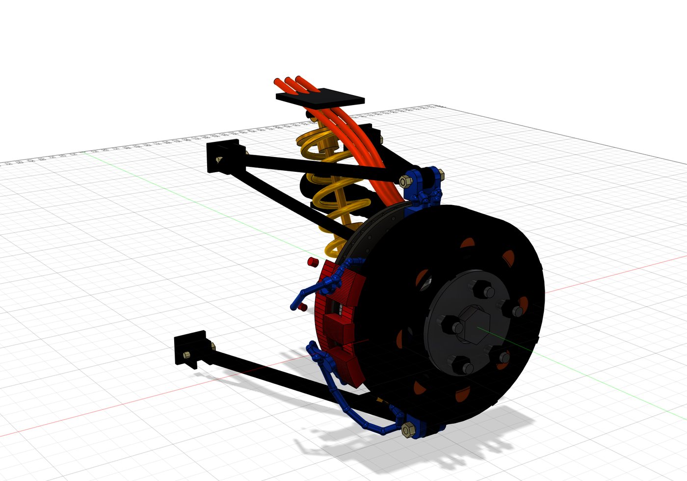
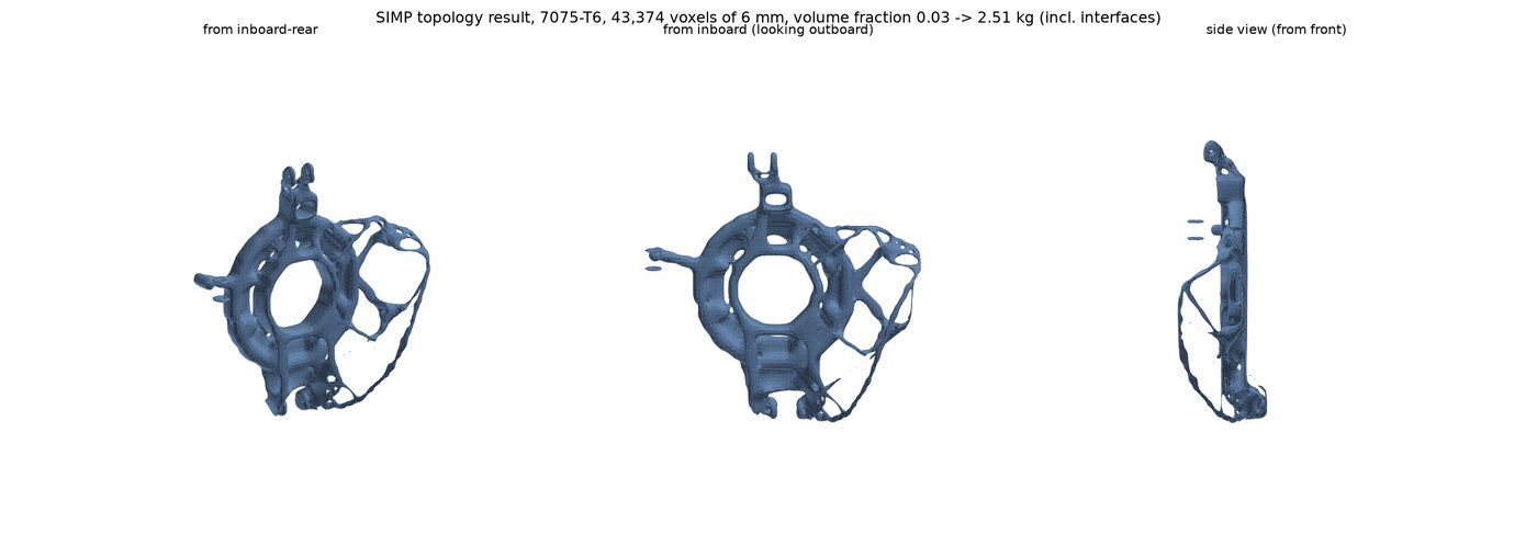
A lightweight steering knuckle and in-wheel motor mount, shaped by topology optimisation.
| Knuckle mass | 2.13 kg |
| Bearing L10 life | 8,690 h |
| Bump steer | < 0.1° |
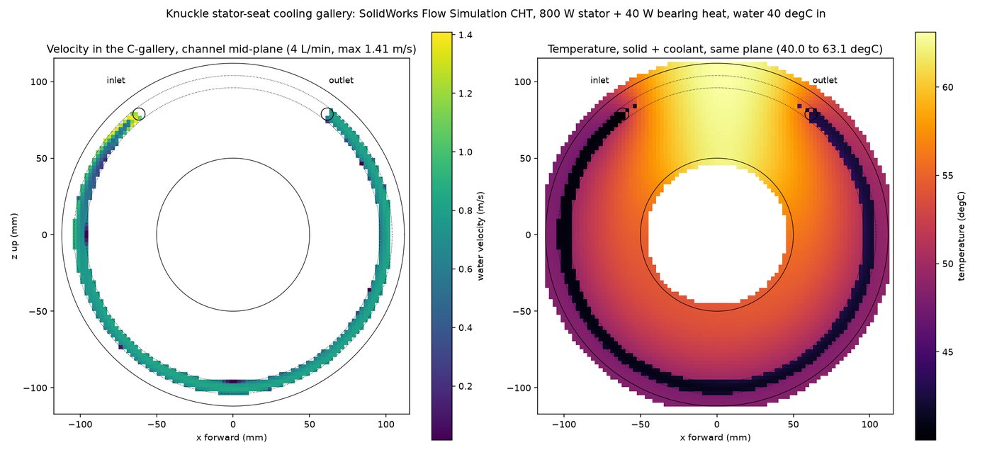
| Bearing seat | 49–64 °C |
Geometry and kinematics are done. The final stress check is paused after the mesher failed on the organic shape.
- Sized the knuckle and motor mount from load cases; checked bearing life and kinematics.
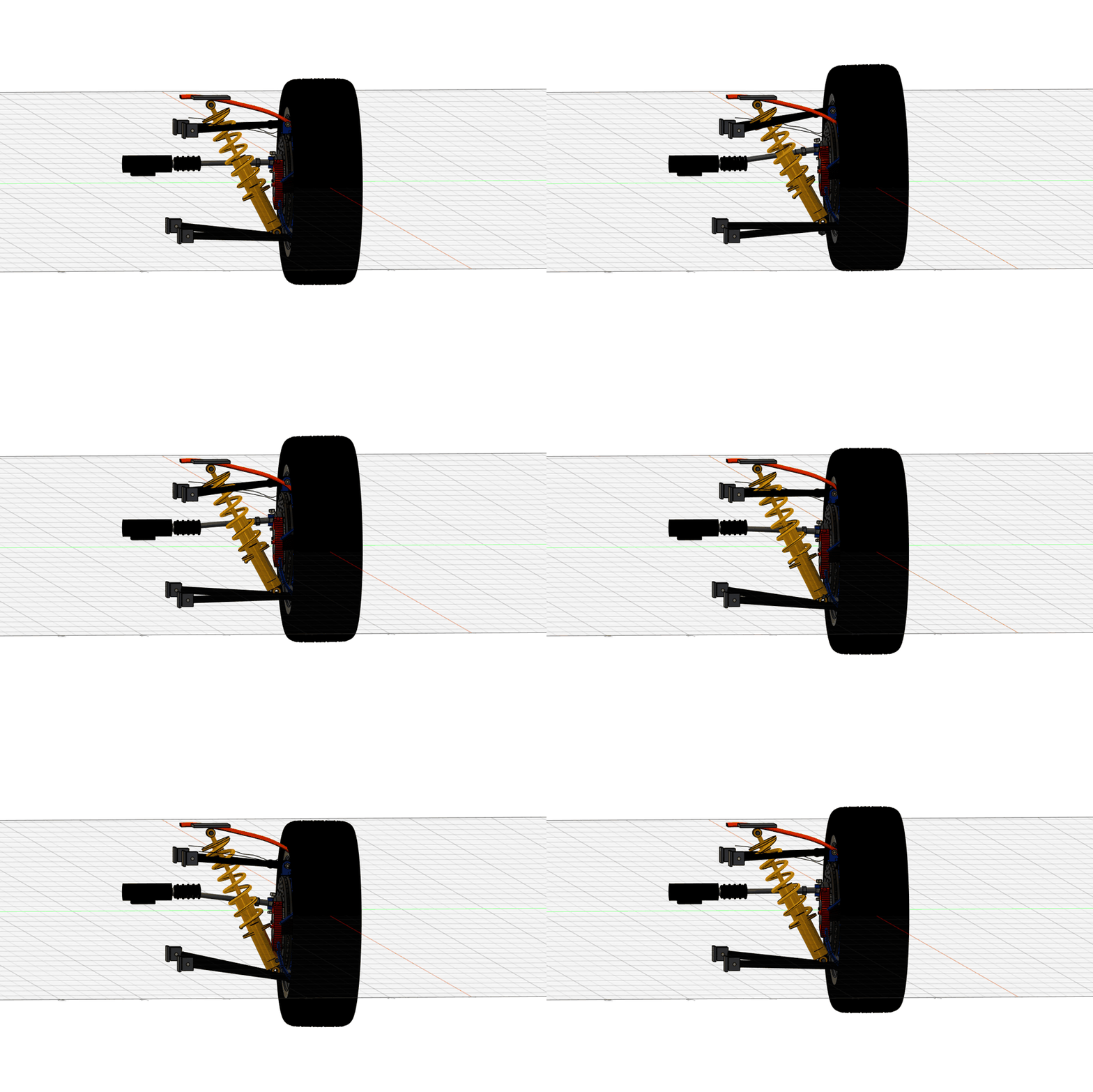
- Wrote a 6-DOF suspension kinematics solver and a 3-D topology optimiser, then rebuilt the knuckle as CAD.
- Built the 33-part Fusion corner assembly and modelled heat transfer in the coolant gallery.